Draft ShapeString tutorial/ru
| Тема |
|---|
| ShapeString (Draft workbench) |
| Уровень |
| Beginner |
| Время для завершения |
| 30 minutes |
| Авторы |
| r-frank |
| FreeCAD версия |
| 0.16.6704 |
| Примеры файлов |
| Смотрите также |
| None |
Introduction
This tutorial has been re-worked for FreeCAD v1.1, but it should be possible to follow the steps for v1.0 as well.
This tutorial describes a method to create 3D text and use it with solid objects in the ![]() Part Workbench. We will discuss how to:
Part Workbench. We will discuss how to:
- insert outlined text with the
 Draft ShapeString tool,
 - position it on geometry using
 Part EditAttachment,
 - extrude it to be a 3D solid with
 Part Extrude, then finally
 - engrave the text by applying a boolean
 Part Cut.
To use ShapeStrings inside the ![]() PartDesign Workbench, the process is essentially the same as with the Part Workbench, but the ShapeString must be placed inside the PartDesign Body. Go to the end of this tutorial for more information.
PartDesign Workbench, the process is essentially the same as with the Part Workbench, but the ShapeString must be placed inside the PartDesign Body. Go to the end of this tutorial for more information.

Final model of the engraved text.
Setup
1. Open FreeCAD and create a new empty document with File → ![]() New Document.
New Document.
- 1.1. Switch to the Part Workbench either with View → Workbench →
 Part Workbench, or with the Workbench Selector
  .
. - 1.2. Press the
 Isometric button, or press 0 in the numerical pad of your keyboard, to change the view to isometric to visualize the 3D solids better.
 - 1.3. Whenever you add objects, press the
 Fit All button, or its hotkey V, F. This will pan and zoom the 3D View so that all elements are visible in the view.
 - 1.4. Hold Ctrl while you click to select multiple items. If you make a wrong selected or want to de-select everything, just click in an empty area in the 3D View.
Create the basic shape
2. Create a rectangular box:
- 2.1. Insert a primitive cube by clicking on
 Cube.
Cube. - 2.2. Select the created
Cubein the Tree View. - 2.3. On the Data tab of the Property View:
- 2.3.1. Change Width to
31 mm.
- 2.3.1. Change Width to
- 2.4. Re-center the view per step 1.3.
3. Create a chamfer:
- 3.1. Select the upper edge (
Edge6) of the elongated face of theCubein the 3D View. - 3.2. Press
 Chamfer.
 - 3.3. In the Chamfer Edges task panel:
- 3.3.1. Verify that Select edges is selected and that the Chamfer type is
Equal distance. - 3.3.2. Change Length to
5 mm. - 3.3.3. Press OK. This will create a
Chamferobject.
- 3.3.1. Verify that Select edges is selected and that the Chamfer type is

Base object created from an edited cube and a chamfer operation.
Insert the ShapeString
4. Create the ShapeString:
- 4.1. Switch to the Draft Workbench.
- 4.2. Click on Shape From Text.
- 4.3. In the ShapeString task panel:
- 4.3.1. Change Text to
FreeCAD. - 4.3.2. Change Height to
5 mm. - 4.3.3. Make sure Font file points to a valid font, (e.g,
/usr/share/fonts/truetype/dejavu/DejaVuSans.ttforC:/Windows/Fonts/arial.ttf).- Note: for more details about working with fonts please refer to the Draft ShapeString page.
- 4.3.4. Reset its location to the origin by pressing Reset Point.
- 4.3.5. Press OK. This will create a
ShapeStringobject.
- 4.3.1. Change Text to
- 4.4. In the Tree View, select
Chamfer. On the View tab, change the value of Visibility tofalse, or press Space on the keyboard. This will hide theChamferobject, so you can see theShapeStringbetter. - 4.5. To see the ShapeString from above change the view by pressing
 Top, or 2 on the keyboard.
 - 4.6. To restore the view to isometric, press Isometric, or 0 on the keyboard.
- 4.7. Reverse step 4.4 to make the
Chamferobject visible again.
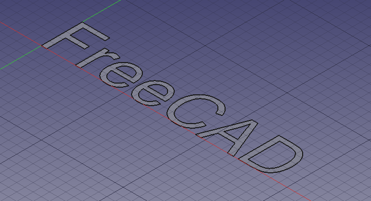
Text created as a ShapeString, that is, a filled compound shape on a plane
5. Move the ShapeString to the Chamfer:
- 5.1. Make sure both the
Chamferobject and theShapeStringobject are visible in the 3D View. If one is not, select it in the Tree View and press Space on the keyboard. - 5.2. Switch to the Part Workbench.
- 5.3. In the Tree View, select
ShapeString. - 5.4. Select Part → Attachment.
- 5.5. In the 3D View, select the chamfered face of the
Chamfer. - 5.6. In the Attachment task panel:
- 5.6.1 Change the Attachment mode to
Inertia 2-3. - 5.6.2 Press OK.
- 5.6.1 Change the Attachment mode to
- 5.8. Make sure
Shapestringis selected in the Tree View. - 5.9. On the Data tab of the Property View:
- 5.9.1. Change Justification to
Middle-Center. - 5.9.2. Expand the Attachment Offset property node and change Angle to
90.0 °.
- 5.9.1. Change Justification to
The ShapeString centered on the chamfered face
Create the engraved text
6. Create a solid object from the ShapeString:
- 6.1. Make sure the Part Workbench is still active.
- 6.2. In the Tree View, select
ShapeString, then press Extrude. - 6.3. In the Extrude task panel:
- 6.3.1. In the Direction section select
Along normal - 6.3.2. In the Length section set Along to
0 mmand Against to1 mm. - 6.3.3. Check the Create solid option.
- 6.3.4. Press OK. This will create an
Extrudeobject.
- 6.3.1. In the Direction section select
- 6.4. Since it has been extruded into the
Chamferobject, the 3D View will look the same as before. Verify the creation of a solid 3D object by temporarily making theChamferobject invisible:- 6.4.1. In Tree View, select
Chamfer. - 6.4.2. Press Space to hide it. You should see a solid 3D object in the shape of the word "FreeCAD".
- 6.4.3. Press Space to make the Chamfer visible again.
- 6.4.1. In Tree View, select
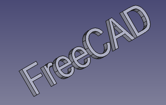
The 3D text after making the Chamfer object invisible.
7. Engrave the text on the geometry:
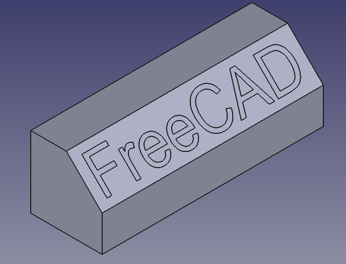
Final model: a chamfered cube, with engraved text created from ShapeString, Extrude, and boolean Cut operations.
Engraving 3D text with the PartDesign Workbench
A similar process as described above can be done with the PartDesign Workbench.
- Create the Draft ShapeString first.
- Create a
 PartDesign Body, make it active, and create a base solid by adding a primitive, or by extruding a sketch with
  PartDesign Pad.
 - Move the
ShapeStringobject into the active body. - Attach the
ShapeStringobject to one of the faces of the solid, or to an edge of the sketch, using Part EditAttachment. - Now create a PartDesign Pad or a
 PartDesign Pocket from the
 ShapeString, in order to produce an additive or a subtractive feature respectively.
See the forum thread How to use ShapeStrings in PartDesign.
Notes
- To create curved text you can use
 Macro FCCircularText.
 - To import text from an SVG file look at the Import text and geometry from Inkscape tutorial.
- Примитивы: Куб(Параллелограмм), Конус, Цилиндр, Сфера, Тор, Полый цилиндр,Примитивы, Связующие формы
- Создание и правка: Выдавливание, Построение фигуры вращения, Отражение, Скругление, Фаска, Создать плоскость из граней, Ruled Surface, Профиль, Sweep, Section, Cross sections, 3D Offset, 2D Offset, Создать полый объект, Projection on surface, Прикрепление
- Булевы операции: Соединить, Разорвать связь, Compound Filter, Булевы операции, Cut, Fuse, Common, Connect, Embed, Cutout, Boolean fragments, Slice apart, Slice, XOR
- Измерительные: Measure Linear, Measure Angular, Measure Refresh, Clear All, Toggle All, Toggle 3D, Toggle Delta
- Инструменты структуры: Part, Group
- Вспомогательные инструменты: Create body, Create sketch, Edit sketch, Map sketch to face
- Инструменты моделирования
- Инструменты данных: Create a datum point, Create a datum line, Create a datum plane, Create a local coordinate system, Create a shape binder, Create a clone
- Аддитивные инструменты: Pad, Revolution, Additive loft, Additive pipe, Additive box, Additive cone, Additive cylinder, Additive ellipsoid, Additive prism, Additive sphere, Additive torus, Additive wedge
- Субстрактивные инструменты: Pocket, Hole, Groove, Subtractive loft, Subtractive pipe, Subtractive box, Subtractive cone, Subtractive cylinder, Subtractive ellipsoid, Subtractive prism, Subtractive sphere, Subtractive torus, Subtractive wedge
- Инструменты трансформации: Mirrored, Linear Pattern, Polar Pattern, Create MultiTransform
- Отделочные инструменты: Fillet, Chamfer, Draft, Thickness
- Бинарные: Boolean operation
- Дополнительно: Migrate, Shaft design wizard, Involute gear
- Инструменты контекстного меню: Set tip, Move object to other body, Move object after other object
- Основные: Создать эскиз, Редактировать эскиз, Прикрепите эскиз, Переориентировать эскиз, Проверить эскиз, Объединить эскизы, Отразить эскиз зеркально, Покинуть эскиз, Просмотр эскиза, Просмотр сечения, Переключить сетку, Переключить привязку, Настройка порядка прорисовки, Остановить операцию
- Геометрия Скетчера: Создать точку, Создать линию по точкам (полилинию), Создать отрезок, Создать дугу от центра, Создать дугу по 3 точкам, Создать эллиптическую дугу, Создать гиперболическую дугу, Создать параболическую дугу, Создать круг по центру, Создать круг по 3 точкам, Создать эллипс от центра, Создать эллипс по 3 точкам, Прямоугольник, Центрированный прямоугольник, Скруглённый прямоугольник, Треугольник, Квадрат, Пятиугольник, Шестиугольник, Семиугольник, Восьмиугольник, Правильный многоугольник, Создать паз, Создать дуговой слот, B-сплайн по контрольным точкам, Периодический B-сплайн по контрольным точкам, B-сплайн по узлам, Периодический B-сплайн по узлам, Переключить вспомогательную геометрию
- Ограничения в Скетчере:
- Размерные ограничения: Размер, Ограничение расстояния по горизонтали, Ограничение расстояния по вертикали, Ограничение Расстояния, Ограничение радиуса/диаметра автоматически, Ограничение Радиуса, Ограничение Диаметра, Ограничение Угла, Ограничение положения
- Геометрические ограничения: Ограничение наложения точек, Ограничение Совпадения точек, Ограничение Точки на объекте, Ограничить горизонтальность/вертикальность, Ограничить горизонталь, Ограничить вертикаль, Ограничение Параллельности, Ограничение перпендикулярности, Ограничить касательную или коллинеарность, Ограничение эквивалентностью, Ограничить симметричность, Ограничение перемещения
- Другие ограничения: Ограничение преломления (Закон Снеллиуса)
- Инструменты ограничений: Переключить ограничения в построительные/основные, Вкл/выкл ограничение
- Инструменты Скетчера: Создать скругление, Создать Фаску, Обрезать ребро, Разделить ребро, Продлить ребро, Внешняя геометрия, Структурная копия, Выбрать начало координат, Выбрать горизонтальную ось, Выбрать вертикальную ось, Переместить / линейный массив, Повернуть / круговой массив, Масштабировать, Сместить геометрию, Симметрия, Удалить выравнивание по осям, Удалить всю геометрию, Удалить все ограничения
- Инструменты для B-сплайн Скетчера: Преобразовать геометрию в B-сплайн, Увеличить степень B-сплайна, Уменьшить степень B-сплайна, Увеличить кратность узла, Уменьшить кратность узла, Вставить узел, Объединить кривые
- Визуализация в Эскизе: Выбрать недостаточно ограниченные элементы, Выделить наложенные ограничения, Выделить ограничиваемую геометрию, Выделить избыточные ограничения, Выделить конфликтующие ограничения, Показать/скрыть вспомогательную окружность для дуг, Показать/Скрыть степень B-сплайна, Показать/Скрыть полигон управления B-сплайном, Показать/скрыть гребень кривизны B-сплайна, Показать/скрыть кратность узлов В-сплайна, Показать/скрыть вес контрольных точек B-сплайна, Показать/скрыть внутреннюю геометрию, Переключить виртуальное пространство
- Дополнительно: Диалоговое окно Скетчера, Настройки, Написание скриптов в Скетчер
- Начинающим
- Установка: Загрузка, Windows, Linux, Mac, Дополнительных компонентов, Docker, AppImage, Ubuntu Snap
- Базовая: О FreeCAD, Интерфейс, Навигация мыши, Методы выделения, Имя объекта, Настройки, Верстаки, Структура документа, Свойства, Помоги FreeCAD, Пожертвования
- Помощь: Учебники, Видео учебники
- Верстаки: Std Base, Arch, Assembly, CAM, Draft, FEM, Inspection, Mesh, OpenSCAD, Part, PartDesign, Points, Reverse Engineering, Robot, Sketcher, Spreadsheet, Surface, TechDraw, Test Framework